Op het YouTubekanaal van Nikhef, het Nederlandse elementaire-deeltjesinstituut dat grote bijdragen levert aan het KM3NeT-onderzoek, staat een serie van tien korte video’s waarin je precies kunt zien hoe een DOM, oftewel een ‘Digital Optical Module’, gebouwd wordt. Voor de liefhebbers embedden we de serie hieronder, met de Engelse beschrijving van de stappen:
Step 1 – Preparations for fixation of the Cooling Mushroom in top hemisphere
The base of a DOM are two 17-inch borosilicate glass hemispheres. Checking air valve fixation. The aluminium milled Cooling Mushroom is positioned with a jig in the top hemisphere.
Step 2 – Fixation Cooling Mushroom in top hemisphere
First the glass hemisphere is aligned horizontally with two spirit levels on the edge. Optical gel is layered between Cooling Mushroom and glass hemisphere. Optical gel is layered because it’s very important not to have any air bubbles. Next day the jig and filler blocks are removed. Last step is placing the Cooling Bar.
Step 3 – Glueing Piezo microphone/sensor in bottom hemisphere
A piezo microphone/sensor is glued into the bottom hemisphere. Dummy PMT (Photomultiplier Tube) holders are used. A hard transparent adhesive is used to ensure the signals pass through the glass properly.
Step 4 – Assembly electrical boards and vacuum test in top hemisphere
In this episode we see the assembly of the two electrical boards and vacuum test of the cable feed through (so called Penetrator) in the top hemisphere.
First the Power Board is placed in the aluminium Cooling Mushroom which outputs 6 watts. Second, the Central Logic Board for the signal processing of all 31 PMTs (Photomultiplier tubes). Between these boards is an aluminium plate as a Faraday cage. The cable feed through (Penetrator) accommodates 2 power cables and 1 fiber optic cable. The Penetrator is designed to withstand a water pressure of 350 bar! Leak tightness of this penetrator in the top hemisphere is tested with vacuum (with intermediate helium spraying)
Step 5 – Fiber Tray and Splicing Fibers in top hemisphere
In this episode we see the pre-assembly of the fiber tray and the fusion splicing process of two optical fibers.
This fiber has an add&drop filter to send signals to and from the 31 PMTs over just one fiber. The fiber tray ensures good guidance of the optical fiber and is made of 3D printed nylon. The ‘outside’ optical fiber will be connected to the ‘inside’ fiber by the so-called fusion splicing. Fiber performance test is done before the splicing. Fiber sheathing is removed, cut straight and cleaned and placed in the splicing machine.
The fusion splicing process is fully automatic. In the fusion splicing process, a specialized fusion splicer machine is used to precisely align the two fiber ends then the glass ends are ‘fused’ or ‘welded’ together using an electric arc heat. This produces a transparent, non-reflective and continuous connection between the fibers enabling very low loss light transmission (Typical loss: 0.1 dB). As a final step, a fiber reinforcement is heated and shrunk to the fiber connection to protect the connection.
Step 6 – Assembly of PMTs in top hemisphere PMT-structure
In this episode we see the assembly of PMTs (PhotoMultiplier Tubes) in the top hemisphere PMT-structure.
PMTs are extremely sensitive detectors of light in the ultraviolet, visible, and near-infrared ranges of the electromagnetic spectrum and can even measure individual photons. PMTs vary in diameter and must be selected for the top or bottom PMT-structure. The PMTs are registered (done by scanning barcodes on PMTs) in the ‘so called’ Detector Integration Assistant system (DIA). This ABS (Acrylonitril Butadien Styreen) PMT-structure consists of 5 injection molded parts which were developed in collaboration with the Plastics Technology Department of Windesheim University of Applied Science.
The top hemisphere consists of 12 PMTs. A sealing rubber is slid over the PMT to ensure later in the assembly process that the optical gel remains on the outside of the PMT structure. To capture as much Cherenkov light as possible, a reflector is placed around the PMT. The ‘Octopus’ readout board (where all PMTs will be connected later) is temporarily attached with a wire in the assembly.
Step 7 – Assembly PMTs in bottom hemisphere PMT-structure
In this episode we see the assembly of the bottom PMT-structure with 19 PMTs (PhotoMultiplier Tubes).
The PMT-structure is a 3D printed (nylon) structure. The O-ring seals are already in the PMT-structure. Here again the sealing rubber ensure later in the assembly process that the optical gel remains on the outside of the PMT-structure. To capture as much as possible Cherenkov light a reflector is placed around the PMT. The Octopus electronic board will be be connected to all 19 PMTs in a later assembly step.
Step 8 – Assembly PMTs in hemispheres & functional tests
In this episode we see the pre-assembly of the PMTs (PhotoMultiplier Tubes) into the top and bottom hemispheres before we do functional tests, to be sure everything works before the PMTs are finally fixed in the hemispheres with optical gel (we will see in the next assembly step).
First the PMTs are cleaned well and made dust-free with compressed air. In the bottom hemispheres the Piezo sensor cable is fed through the PMT-structure. Then all PMTs will be connected to the Octopus Board. After placing the top PMT-structure in the hemisphere the Piezo sensor and LED are connected. The LED (so called ‘Nanobeacon’) acts as an additional way to calibrate. The light that is emitted can be detected by a DOM further on the Detector Unit (DU). A Detection Unit (DU or string) is a collection of 18 DOMs connected by an electro-optical cable and arranged along a vertical structure with two ropes.
Two DOMs (Digital Optical Module) – 4 hemispheres – simultaneously undergo a functional test. The test checks whether the compass and the piezo sensor are working, accessibility of the PMTs and the temperature of the electronics (not getting too hot).
Step 9 – Putting optical gel between PMTs and glass hemisphere
In this episode we see first the sealing of the top PMT-structure to the cooling mushroom and then putting optical gel between the PMTs and glass hemisphere to permanently fix the 31 PMTs in the hemisphere.
After a successful functional test, the PMTs will be permanently fixed in the hemisphere with optical gel which is highly transparent and remains flexible. ‘Transparent’ to allow the photons to pass through to the PMTs as well as possible and ‘flexible’ to accommodate temperature changes and size changes of the glass under high pressure (max. 350 bar) underwater.
The top PMT-structure is first sealed to the cooling mushroom with normal silicone sealant to avoid getting optical gel behind the PMTs and electronics. The hemispheres are placed level and fixed in position. The optical gel will be fed to the bottom via a feed funnel and a tube in the PMT-structure. The two components optical gel is mixed in the syringe. Important that no air bubbles get in the optical gel. Curing takes about 4 hours.
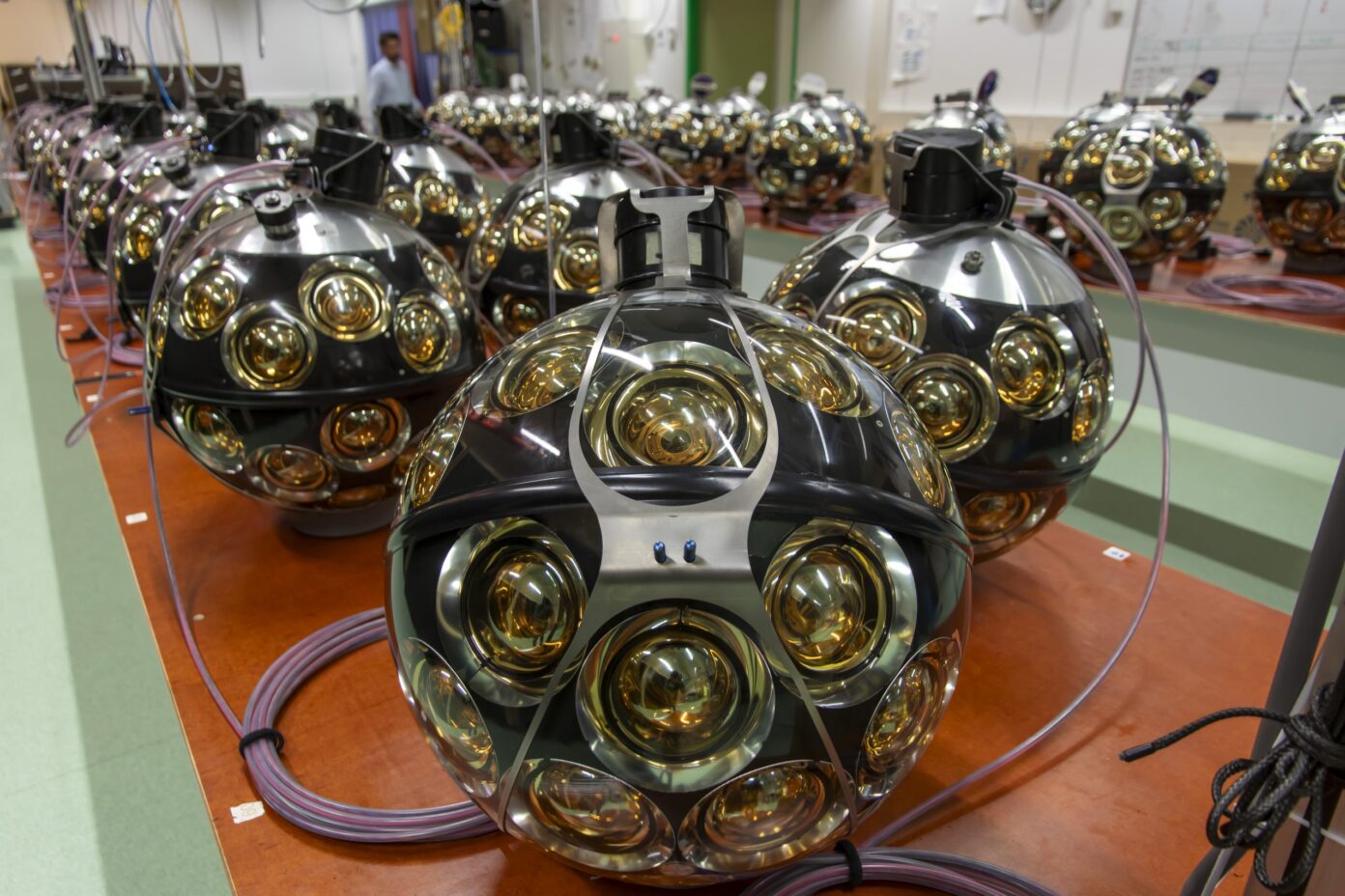
Step 10 – Closing a DOM
In this episode we see the closing of a Digital Optical Module (DOM), consisting of a top hemisphere with 12 PhotoMultiplier Tubes (PMTs) and a bottom hemisphere with 19 PMTs.
First, all materials needed before, to putting gel between the PMTs and the glass hemispheres, are removed and the interfaces (contact surfaces) of the glass hemispheres are cleaned. To close a DOM, a so-called ‘Closing Device’ was developed at Nikhef. The bottom hemisphere gets sucked in and will be turned over. The top hemisphere is placed on a vertical adjustable cylinder. The bottom electronic board slides into the top cooling bar and will be definitively fixed with a screw. the two surfaces of the hemispheres are so flat that a vacuum of 0.2 bar in the DOM fix them together. The closing edge is protected against seawater with 2 special tapes. The two hemispheres are permanently held together with the Titanium so-called ‘Collar’.
Assembly of a DOM is now ready and will be stored in a dark cabinet (to prevent light aging of the PMTs) to be assembled later in the assembly together with 18 other DOMs into a Detector Unit (DU).